Getting Started with Forlinx OK6254-C Board with The TI AM6254
Here today we’ll present the Forlinx OK6254 board to you about its interfaces, and how to boot it. Before all of the operations, we kindly suggest you reading hardware manual provided by Forlinx.
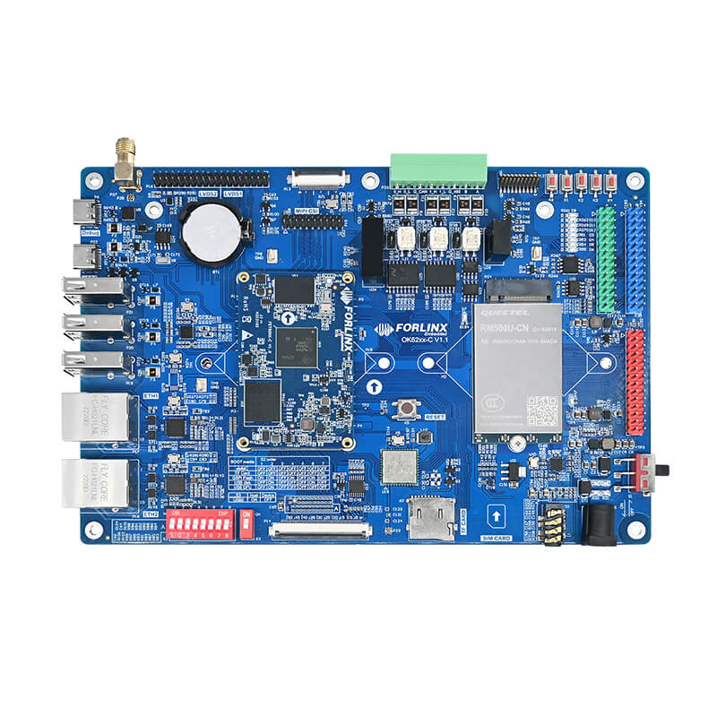
Firstly, let’s have a look at the board as a whole.
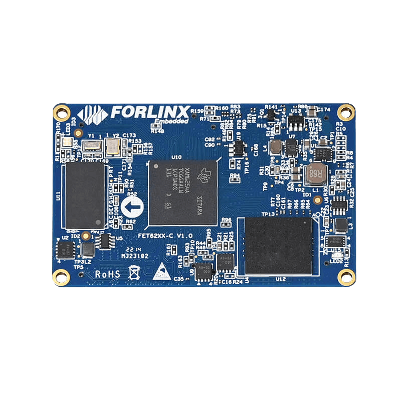
At the heart of the board is the system on module FET6254-C which is plugged on carrier board, and it integrates some main components such as processor, RAM, Flash and PMIC on it. At the heart of the SoM is ASIC from Texas Instruments AM 6254 that is a quiet new chip; it was released last year. It features four Cortex-A-53 cores for running Linux operating system, and one Cortex-M core for real-time operations and device management.
The board has DDR4 RAM, so you can choose between 1 Gigabyte or 2 Gigabyte version. It has a flash storage, so we have a 8 Gigabyte eMMC storage. This is only the system on a module, which is plugged on this carrier board.
The carrier board has two Gigabyte Ethernet ports, and DIP switches for adjusting the boot mode. If all dip switches, the device will boot from the eMMC memory, but we have other boot options, for example, we can use the SD card to boot, and we can adjust the boot mode. There is a small table showing the available booting modes and the dip switch settings for them.
On the carrier board, there are various connectors available for users, such as LCD display connector and Wi-Fi & BT, reset key, SD card slot, SIM card slot, Audio jack, DC12V power key, some user keys and user LEDs. We can use them to debug the board, and we can use JTAG connector also.
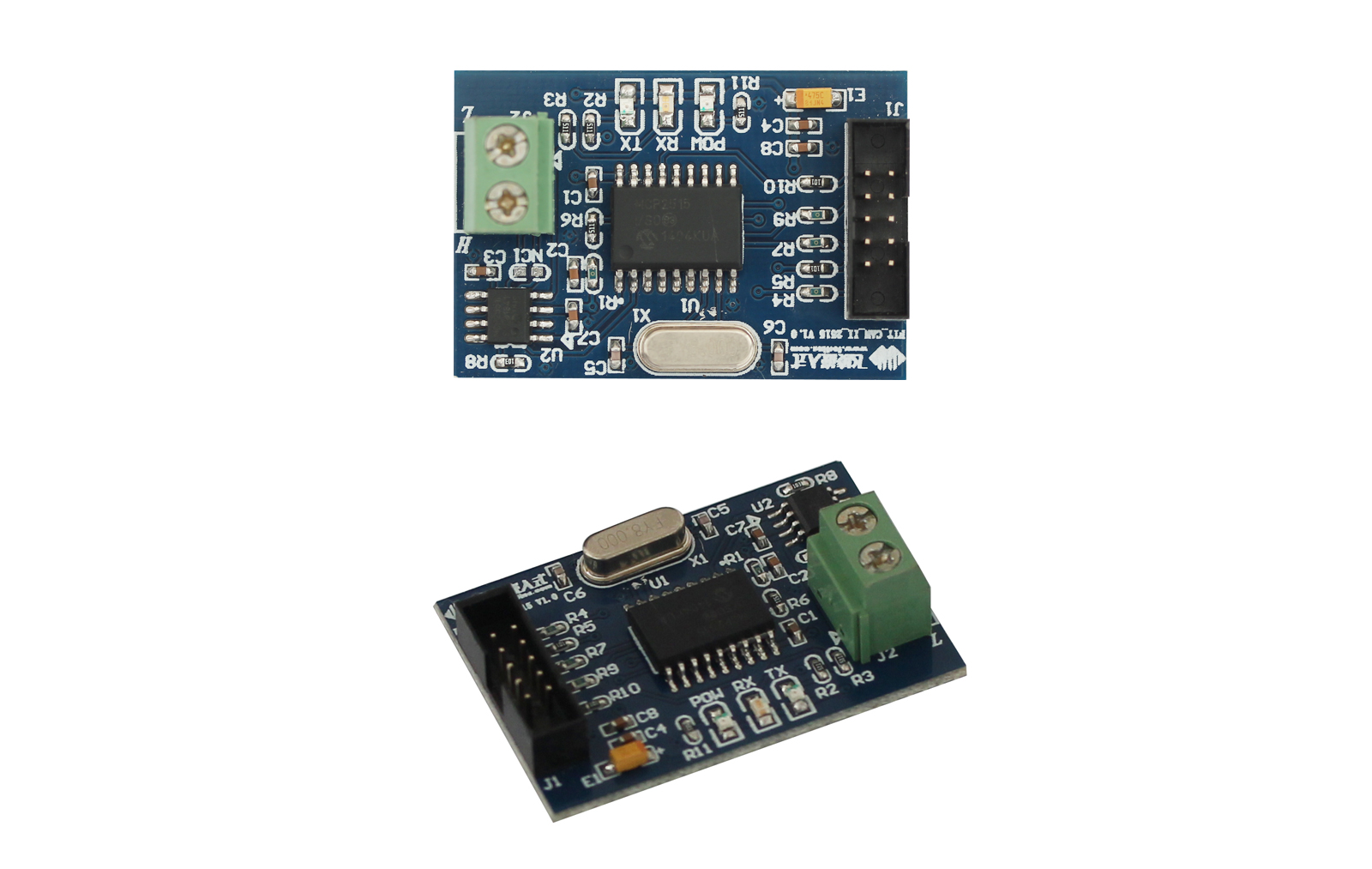
From the above picture we can see that it is not soldered, but on the board the pin header is already soldered down. There here it has two CAN interfaces and one RS485 interface available.
It has LVDS for connecting a display and a RTC clock available. Then a USB port for accessing the serial console of the Linux kernel, so the over serial Port debug information is available, and you can even access a TTY over the serial part here. It has USB OTG free USB 2. 0 HOST connectors based on a USB hub, also what is a cool is that there is an M2 slot on it, over which we can connect PCIe cards in M2 form factors such as 4G or 5G mode plugged into it.
Then the next step, we’ll do some operations.
We can connect a RGB LCD on it, when we power up the board from the eMMC memory a demo video for Forlinx will play. Here we connect USB to have a new serial connection on the device. Here, we have two UARTs, and one is used for accessing the TTY over serial, then let’s open it up with screen and the baud rate is 115200.
We need to input the password, then power on the board. Here we can see U-Boot starting , and now it's booting from the embedded multimedia card. We can see the system messages output; now a program has started and LED flashes, and on display, we should see an image video for Forlinx embedded.
Then we have accessed a TTY, the username is root and we don't need to give it a password. Take a look at the home folder, we’ll see a video file here and the rest are some things to be tested on the board.
Let's look at some more interesting stuff. First let's take a look at the processor, so in proc/cpuinfo we get some information. It's a quad-core processor, so we have four process of course as below.
Then let's take a look at the memory with free, and I want to have it readable, we have 1 Gigabyte of memory available(2GB is optional also). As for eMMC memory, here we have 6.8 gigabytes complete size and 4.6 gigabytes is still available, which is quite a lot even,and the image video is quite big too.
The image video is already 120MB in size. Let’s look at the used memory ,it’s about 400MB are used. It seems a little bit much, but you have to know a video is playing here, and if you take this into account, this memory is really okay.
Next, let's see which network interfaces are available. We have two Ethernet connectors on carrier board and they are Gigabit, and we have a CAN interface available too, which is pretty cool and some other connectors.
Then, we can know what drivers are loaded by looking at the provided device files. We have three GPIO chips available,and we have 5 IIC interfaces available, and we even have an SPI interface available.
If we go into this class remote processors, we can see free remote processors listed. The first one is M4 core.If we catch the name here, and we can see the name is M4 FSS, so this is the M4 core, and over the system as we will later load a sample program to this. It’s a really cool board and a really good platform for getting started with programming embedded Linux.
That’s all for this time, we’ll do further testing next time.
TI AM6254 Board Video Introduction:
Presenting the Forlinx OK6254-C Board with the TI AM6254 by Youtuber Johannes 4GNU_Linux
Forlinx OK6254 Development board purchase order link:
Alibaba
TI AM6254 Board Details:
Forlinx OK6254-C Board
If you have any questions, please
Contact us


