Using SPI for Interfacing with Digital RTD Temperature Sensors on the RK3562J Platform
The MAX31865 is a simple and easy-to-use thermistor-to-digital output converter, optimized for platinum resistance temperature detectors (RTD). External resistors set the sensitivity of the RTD, while a high-precision Δ-Σ ADC converts the ratio of the RTD resistance to the reference resistance into a digital output. The MAX31865 input has overvoltage protection of up to ±45V and provides configurable detection for RTD and cable open-circuit and short-circuit conditions. It is suitable for a wide range of high-precision temperature devices in medical, industrial, temperature computation, satellite, meteorological, resistance measurement, and other applications.
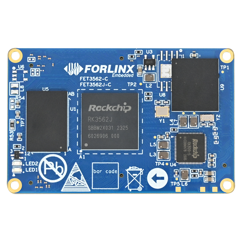
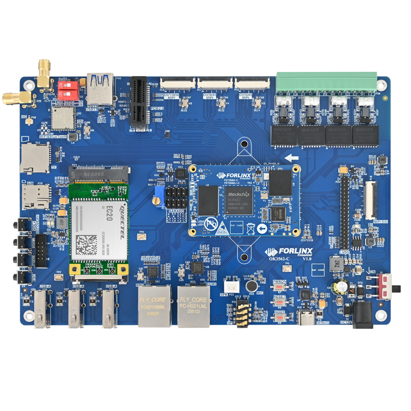
The latest OK3562J-C single board computer from Forlinx Embedded has reserved the SPI2 interface, located on the P8 pin header:
SPI2_CLK_M0,
SPI2_CSN0_M0,
SPI2_MOSI_M0,
SPI2_MISO_M0.
This article will introduce how to use SPI2 on the OK3562J-C development board to interface with the MAX31865 (digital RTD temperature sensor) chip.
1. Modification Approach
The approach to adding an SPI device is as follows:
Add a description in the device tree → Corresponding device driver in the device tree description → Add the device driver to the kernel.
2. Modification Method
(1) The MAX31865 module supports 2-wire, 3-wire, and 4-wire connection methods. The 3-wire connection method is utilized here, which is a compromise requiring one less wire than the 4-wire method. To compensate for the voltage drop across the leads, the voltage between (RTDIN+ and RTDIN-) will be reduced by the voltage between FORCE+ and RTDIN+. Sampling at the input is achieved using FORCE2. If the cable resistance has good consistency, it can eliminate errors introduced by the cable resistance.
Before wiring, the module needs to be soldered to configure it in a 3-wire mode as shown in the diagram below.
(2) Add the relevant descriptions for the MAX31865 in the device tree. Since we are using a 3-wire connection, we need to add the maxim,3-wire parameter.
3. Compiling the Driver as a Module
(1) Create a folder named max31865 under the /drivers directory in the kernel source, and add the max31865.c and Makefile files.
(2) Modify the parent directory /kernel/drivers/Makefile, and perform a full compilation operation. The modifications are as follows:
The content is: /drivers/max31865/Makefile:
obj-m += max31865.o
Add the following code to /kernel/drivers/Makefile:
obj-y += max31865
Then execute the ./build.sh kernel script to compile the kernel, which will generate the .ko module in the /drivers/max31865 directory.
(3) Copy max31865.ko to the OK3562J-C development board and execute insmod max31865.ko to load the module.
4. Test
Use a 22Ω resistor to simulate the platinum resistance and run the following command to check the raw ADC value:
cat /sys/bus/iio/devices/iio:device2/in_temp_raw
The ADC value for the 22Ω resistor should be observed as 1655. Comparing this with the values in the chip manual indicates that this is normal, corresponding to a temperature of approximately -190℃.
At this point, the new MAX31865 (digital RTD temperature sensor) device has been successfully added, and applications can be developed based on the raw ADC values to correspond to the measured temperature.
The above is the method of using SPI2 to mount MAX31865 (digital RTD temperature sensor) device on OK3562J-C development board. It is hoped that this will be helpful for project development.