How to Boot the RK3562J on the M-Core?
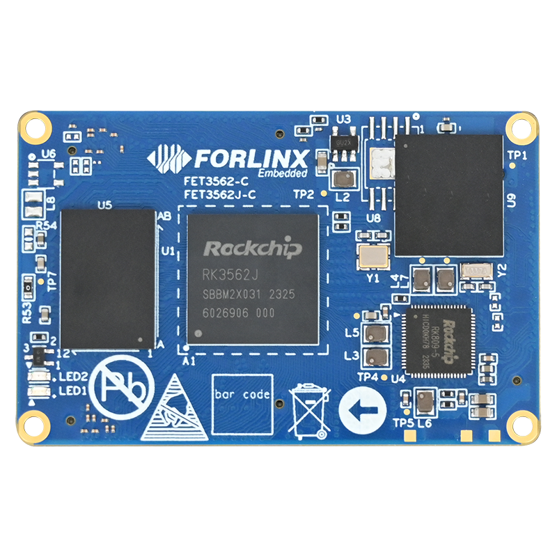
FET3562J-C SoM based on Rockchip RK3562 series processor is a product designed for industrial automation and consumer electronics equipment. With its powerful functions and flexibility, it has attracted wide attention from customers in various industries since its launch. This article will introduce in detail how to start and test the MCU of RK3562J processor, and help engineers better understand this chip through practical operation steps.
RK3562J Processor Overview
RK3562J processor uses a 4*[email protected] + Cortex-M0 @ 200MHz architecture. Among them, the four Cortex-A53 cores are the main cores responsible for handling complex operating system tasks and applications. In contrast, the Cortex-M0 cores serve as auxiliary cores running a bare-core system capable of fast response and control for tasks with high real-time requirements.
Preparations for Launching the M0 Core Firmware
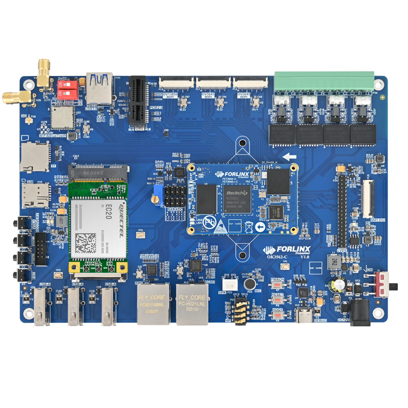
At present, the M0 kernel firmware is not started by default on the embedded OK3562J-C development board. Therefore, we need to go through a series of steps to configure and start the M0 core. The following are the specific steps.
1.U-Boot Modification
In theory, we need to open the AMP (Asymmetric Multiprocessing) compilation macro, but because the U-Boot of the embedded OK3562J-C development board has been configured with the AMP function by default, the user does not need to modify any U-Boot.
2. Kernel Modification
(1) Toolkit Installation
First, we need to install the SCons toolkit for later compilation. It can be installed with the following command:
forlinx@ubuntu:~$ sudo apt-get install scons
(2) Add AMP Device Tree Calls
OK3562J-C board has been added with a call to the AMP device tree. It's content can be viewed through the relevant configuration files.
forlinx@ubuntu:~$ cd /home/forlinx/work/OK3562-linux-source/
forlinx@ubuntu:~/work/OK3562-linux-source$ vi kernel-5.10/arch/arm64/boot/dts/rockchip/OK3562-C-common.dtsi
+include "rk3562-amp.dtsi"
rk3562-amp.dtsi includes:
/ {
/* Device description */
    rockchip_amp: rockchip-amp {
        compatible = "rockchip,amp";
        clocks = <&cru FCLK_BUS_CM0_CORE>, <&cru CLK_BUS_CM0_RTC>,
            <&cru PCLK_MAILBOX>, <&cru PCLK_INTC>,
        //  <&cru SCLK_UART7>, <&cru PCLK_UART7>,
            <&cru PCLK_TIMER>, <&cru CLK_TIMER4>, <&cru CLK_TIMER5>;
        //pinctrl-names = "default";
        //pinctrl-0 = <&uart7m1_xfer>;
        amp-cpu-aff-maskbits = /bits/ 64;
        amp-irqs = /bits/ 64 ;
        status = "okay";
    };
/*Some reserved memory areas are defined */
    reserved-memory {
        #address-cells =;
        #size-cells =;
        ranges;
        /* remote amp core address */
        amp_shmem_reserved: amp-shmem@7800000 {
            reg =;
            no-map;
        };
        rpmsg_reserved: rpmsg@7c00000 {
            reg =;
            no-map;
        };
        rpmsg_dma_reserved: rpmsg-dma@8000000 {
            compatible = "shared-dma-pool";
            reg =;
            no-map;
        };
        /* mcu address */
        mcu_reserved: mcu@8200000 {
            reg =;
            no-map;
        };
};
/* Implementing the Rockchip RPMsg function */
    rpmsg: rpmsg@7c00000 {
        compatible = "rockchip,rpmsg";
        mbox-names = "rpmsg-rx", "rpmsg-tx";
        mboxes = <&mailbox 0 &mailbox 3>;
        rockchip,vdev-nums =;
        /* CPU3: link-id 0x03; MCU: link-id 0x04; */
        rockchip,link-id =;
        reg =;
        memory-region = <&rpmsg_dma_reserved>;
        status = "okay";
    };
};
3. Generating Configuration Files
Next, we need to generate a configuration file for the M0 core firmware. In the RTOS source directory, generate the required configuration file by copying the default configuration file and running the SCons menu configuration interface. Although no additional configuration is required in this example, the user can configure it as needed.
forlinx@ubuntu:~/work/OK3562-linux-source$ cd rtos/bsp/rockchip/rk3562-32
forlinx@ubuntu:~/work/OK3562-linux-source/rtos/bsp/rockchip/rk3562-32$ cp board/rk3562_evb1_lp4x/defconfig .config
forlinx@ubuntu:~/work/OK3562-linux-source/rtos/bsp/rockchip/rk3562-32$ scons --menuconfig
After opening the graphical configuration interface, you can exit directly without configuration.
If there are other functional requirements, you can exit and save after corresponding configuration.
forlinx@ubuntu:~/work/OK3562-linux-source/rtos/bsp/rockchip/rk3562-32$ cp .config board/rk3562_evb1_lp4x/defconfig
forlinx@ubuntu:~/work/OK3562-linux-source/rtos/bsp/rockchip/rk3562-32$ cp rtconfig.h board/rk3562_evb1_lp4x/defconfig.h
4. Source Code Compilation
After generating the configuration file, we can start compiling the source code. By running the build script, select the appropriate defconfig configuration and compile the Linux system and M0 core firmware separately. After successful compilation, amp. img image files will be generated in the specified directory.
forlinx@ubuntu:~/work/OK3562-linux-source/rtos/bsp/rockchip/rk3562-32$ cd ../../../../
forlinx@ubuntu:~/work/OK3562-linux-source$ ./build.sh chip
Log colors: message notice warning error fatal
Log saved at /home/forlinx/work/3562/git/OK3562-linux-source/output/sessions/2024-08-27_15-48-21
Switching to chip: ok3562
Pick a defconfig:
1. forlinx_defconfig
2. forlinx_ok3562_linux_defconfig
3. forlinx_ok3562_linux_mcu_defconfig
4. forlinx_ok3562_linux_rtos_defconfig
Which would you like? [1]: 4   //Select the fourth
forlinx@ubuntu:~/work/OK3562-linux-source$ ./build.sh rtos
forlinx@ubuntu:~/work/OK3562-linux-source$ ./build.sh mcu
After compilation, generate a amp. img in the rockdev directory:
forlinx@ubuntu:~/work/OK3562-linux-source$ ls rockdev/
amp.img  boot.img  linux-headers.tar  MiniLoaderAll.bin  misc.img  oem.img  parameter.txt  recovery.img  rootfs.img  uboot.img  update.img  userdata.img
Flashing Image
Copy the generated amp. img image file to the computer, and switch the development board to the flashing mode. Use the flash tool to configure the path to amp.img.
Click "Device Partition Table" and click "Execute" after successful reading.
Startup Validation
Press the spacebar to enter the U-Boot menu when restarting the board. In the U-Boot menu, enter 3 to configure amp start on.
Enter 1 to restart the development board. During the boot process, observe the printouts of the U-Boot stage, if printouts related to the M0 core firmware boot are seen, the M0 core firmware has been successfully booted using U-Boot.
Summary
The above operation is simply to start the M0 core and print the information. In fact, the M0 core is very powerful, supporting UART, PWM, I2C, SPI and other peripheral interfaces. (At present, Forlinx Embedded has no more M0 core interface test routines. If there are relevant requirements,please contact the technical support to obtain the official information of Rockchip for in-depth study and development.)
Hope this article can give you a better understanding of the M0 core of the RK3562J processor and help you in your subsequent development work. Click on the image below to learn more about the FET3562J-C SoM.
Dear friends, we have created an exclusive embedded technical exchange group on Facebook, where our experts share the latest technological trends and practical skills. Join us and grow together!