OK536-C Single Board Computer
CPU: Allwinner T536
Architecture: 4x [email protected]+RISC-V@600MHz
Frequency: 1.6GHZ
RAM: 1GB/2GB LPDDR4
ROM: 8GB/16GB eMMC
System: Linux 5.10
OK536-C Single Board Computer Based on Allwinner T536 Processor
OK536-C single board computer(SoM) / development board, based on Allwinner's industrial-grade T536 processor, features a modular SoM + carrier-board architecture with a 320-pin interface. Utilizing four 80-pin board-to-board connectors, it provides comprehensive I/O access through an optimized pin assignment strategy. This design incorporates comprehensive functional optimizations while maintaining developer-friendly accessibility, significantly accelerating secondary development cycles. The modular architecture simplifies system integration and offers engineers a robust evaluation platform, providing a solid technical foundation for project prototyping and custom hardware design.
OK536-C SBC
Allwinner’s New Generation High-Performance Chip
T536 integrates higher-performance application cores, an independent RISC-V MCU, and supports features
such as 2TOPS NPU, secure boot, full-path ECC, AMP, Linux-RT, and LocalBus. It can accelerate edge machine learning applications.
Rich Resources
AMP & Multi-core Heterogeneous
It integrates a quad-core Cortex-A55 and a 64-bit XuanTie E907 RISC-V MCU,
and supports Linux RT + FreeRTOS + bare-metal code to meet the requirements of high performance and real-time control simultaneously.
NPU: 2TOPS Computing Power
It is equipped with NPU with a computing power of up to 2TOPS, providing strong support for edge computing applications.
All Pins Are Exposed
All the pins of the CPU are exposed through a high-speed BTB connector. Users can flexibly configure the hardware according to specific application scenarios,
enhancing the adaptability and customization ability of the processor to meet the different functional requirements of various products in different fields.
Parallel Bus Local Bus
It supports the parallel bus Local Bus, with a high data read/write rate of 16bit@100M or 32bit@50M, which facilitates communication between ARM and FPGA.
Security Features
Built-in Trustzone and secureboot to ensure system security and data encryption.
Full-path ECC technology to provide error checking and correction for data transmission from the CPU to DDR, ensuring data integrity and preventing illegal tampering.
ISP Greatly Improves Image Quality
It integrates ISP technology, supporting technologies such as 8M@30fps, WDR, and 3DNR, and can provide clear and accurate image data.
Continuously Updated User Documentation
It provides users with comprehensive development resources,
including software and hardware development materials, FAQ manuals, pin multiplexing comparison tables, hardware manuals, test routines, and carrier board schematics.
The completeness of the documentation greatly simplifies the development process and makes product production more efficient and convenient.
Application Scenarios
▊ Allwinner T536 SoM & SBC Video
New FET536-C SoM Release | Power up your Industry 4.0 | Allwinner T536 Processor
▊ Hardware Features
|
FET536-C System on Module Basic Features |
||
|---|---|---|
|
Processor |
Allwinner T536 CPU: 4xCortex-A55 NPU: 2TOPS RISC-V: XuanTie E907@600MHz VPU: Video decoding Video encoding |
|
| RAM |
1GB/2GB LPDDR4 |
|
|
ROM |
8GB/16GB eMMC |
|
|
Operating Temperature |
-40℃~+85℃ |
|
|
Working Voltage |
DC 5V |
|
|
Connection |
Board-to-board connector (4×80Pin), pin pitch: 0.5 mm, mating height: 2.0 mm) |
|
|
Dimensions |
45mm×68mm |
|
|
OS |
Linux 5.10 |
|
|
FET536-C System on Module Functional Parameters |
||||
|---|---|---|---|---|
|
Function |
QTY |
Spec. |
||
|
Parallel CSI |
≤1 |
Supports 8/10/12/16 bit width |
||
|
MIPI CSI |
≤4 |
8M@30fps RAW12 2F-WDR, maximum size 3264(H) x 2448(V) |
||
|
MIPI DSI(1) |
≤1 |
Supports 4-lane MIPI DSI,1920x1200@60fps |
||
|
RGB LCD(1) |
≤1 |
DE/SYNC mode,1920x1200@60fps |
||
|
LVDS(1) |
≤2 |
Supports dual link 1920 x 1080@60fps,single link 1366 x 768@60fps |
||
|
SDIO |
≤2 |
SMHC0,used for SD card |
||
|
Audio |
≤1 |
Built-in audio codec supports 1 x differential LINEOUT output |
||
|
I2S |
≤4 |
Supports master/slave mode with sampling rate from 8kHz to 384kHz |
||
|
DMIC |
≤1 |
Supports 8 channels with sampling rates from 8kHz to 48kHz |
||
|
OWA IN/OUT |
≤1 |
Single line audio |
||
|
USB3.1(2) |
≤1 |
USB3.1 OTG,5Gbps |
||
|
PCIe2.1(2) |
≤1 |
Supports RC & EP,1-lane,5Gbps |
||
|
USB2.0 DRD |
1 |
Supports master-slave, high-speed, 480Mbps |
||
|
USB2.0 HOST |
1 |
Main mode only, supporting high-speed, 480Mbps |
||
|
GMAC |
≤2 |
Support RMII/RGMII interface, support rate 10/100/1000 Mbit/s |
||
|
CAN-FD |
≤4 |
Supports CAN-FD and CAN2.0B |
||
|
Local Bus |
≤1 |
Supports 8/16/32 bit width, up to 100MHz bus clock |
||
|
SPI |
≤5 |
Supports master/slave mode, up to 100MHz clock |
||
|
TWI(3) |
≤8 |
Compatible with I2C standard, standard mode 100 kbit/s, fast mode 400 kbit/s |
||
|
UART(4) |
≤17 |
Compatible with 16450/16550 |
||
|
GPADC |
≤28 |
12-bit sampling resolution and 10-bit accuracy, maximum sampling rate 2MHz |
||
|
LRADC |
1 |
6-bit sampling resolution, 2KHz sampling rate, used for key detection |
||
|
TPADC |
≤1 |
4-wire resistive touch, 12 bit SAR type AD conversion |
||
|
PWM |
≤34 |
Output frequency 0 ~ 24MHz or 0 ~ 100MHz |
||
|
LEDC |
≤1 |
Control LED light, programmable output high and low width, data up to 800kbit/s |
||
|
IR TX |
≤1 |
Infrared output |
||
|
IR RX |
≤5 |
Infrared intput |
||
|
GPIO |
≤196 |
|||
Note: The parameters in the table are hardware design or theoretical CPU values.
1. RGB, LVDS, MIPI-DSI are multiplexed. Please read the chip data sheet or the pin multiplexing table;
2. USB3.1 and PCIe interfaces are multiplexed, and only one of them can be used at a time;
3. S-TWI0 is occupied by the SoM, and the carrier board cannot be used at a time;
4. UART0 is used to debug the serial port. It is recommended that the user keep the design.
▊ OK536-C Carrier Board
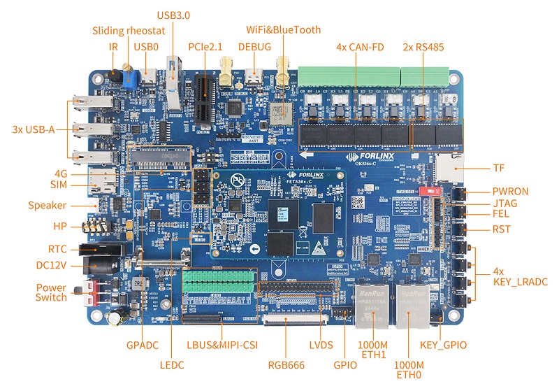
| OK536-C Single Board Computer Features | |||
|---|---|---|---|
|
Peripheral interfaces |
QTY |
Spec. |
|
|
LCD(1) |
1 |
RGB 666 18-bit, SoM supports up to RGB888 24-bit, 1080p @ 60fps |
|
|
LVDS(1) |
1 |
Dual Octal with 1080p @ 60fps |
|
|
MIPI DSI(1) |
1 |
LVDS to MIPI to board, supporting 4lane and 1080p @ 60fps; |
|
|
Ethernet |
2 |
10/100/1000Mbps adaptive,RJ-45 interface |
|
|
TYPE-C(DEBUG) |
1 |
Convert debugging UART to USB export, debug CPUS, CPUX and RISC-V respectively |
|
|
TYPE-C(USB0)(2) |
1 |
Native USB0 interface supports OTG multiplexed with the USB hub, allowing only one to be used at a time. |
|
|
USB Host(2) |
3 |
Expanded by hub, USB 2.0 (supporting up to 480 Mbps), multiplexing with native USB0, only one to be used at a time. |
|
|
USB3.0(3) |
1 |
Led out by USB3.0-A socket, multiplexing with PCIE pin, only one to be used at a time. |
|
|
PCIE2.1(3) |
1 |
Led out by PCIE X1 socket, multiplexing with USB3.0 pin, only one to be used at a time. |
|
|
TF |
1 |
Supports SD3.0 |
|
|
MIPI CSI |
3 |
Multiplexed with Local Bus. External FIT-CAM_E module board needed, with 1 x 4Lane MCSI and 2 x 2Lane MCSI. |
|
|
WiFi & BlueTooth |
1 |
On-board AW-CM358SM, 2.4G/5G dual-band Wi-Fi, BT5.0, and audio. |
|
| PWM |
1 |
Connected to the LCD backlight adjustment |
|
|
GPADC |
14 |
1.8V, with a sliding potentiometer on carrier board for convenient testing. |
|
|
RTC |
1 |
On-board CR2032 battery, power-off keep time |
|
|
Audio |
2 |
1 x four-section headphone jack, with a built-in HP (headphone) and MIC (microphone). |
|
|
KEY |
8 |
Includes reset, flashing, switch, GPIO key, LRADC key X4 |
|
|
CAN-FD |
4 |
CAN-FD with protection circuit |
|
|
485 |
2 |
With automatic send/receive control with protection circuitry |
|
|
IR |
1 |
IR_RX, sample rate 1MHz, 64*8bits cache |
|
|
Local Bus |
1 |
Led out via a 90-pin connector, 8/16/32-bit width data transmission, synchronous read/write 128X8 FIFO. Also led out via 2.54-mm pin headers. Multiplex with MIPI-CSI, and only one to be used at a time. |
|
|
4G(2) |
1 |
Extended by USB2.0 hub multiplexed with USB0 |
|
|
GPIO |
5 |
Pinout |
|
|
LEDC |
1 |
Independent controllable light |
|
|
CPUX-JTAG |
1 |
Pinout |
|
|
CPUS-E902-JTAG |
1 |
Pinout |
|
|
RISC-V (E907) UART |
1 |
Pinout |
|
▊ Downloads
Catalog:
Forlinx Catalog Manual
Product Brief:
FET536-C SoM and OK536-C SBC Introduction
▊ Accessories
Please click here to get more information about the supported modules and accessories.
▊ Technical Support
1. Files to be provided after buying
Hardware related: datasheet, user guide, carrier board schematic, carrier board PCB, SoM pinmux;
Firmware related: OS image, testing demo, source code, manual;
Compiling environment
2. Fast response after-sale technical support service
Contact Us
Welcome to get in touch with us, our experts will reply to your email within 24 hours.
▊ How To Buy
1. Order Online
We have an online store on Alibaba, please contact us for details.
2. Order Offline
Please send your inquiry to [email protected];
3. Payment Terms
100% T/T in advance.
▊ Shipment
1. Delivery: Goods will be shipped by express upon the receipt of the payment;
2. Lead time: Goods will be shipped out within five working days for sample orders and 6 weeks for bulk orders;
3. Shipping charge: Buyers should bear the shipping cost.
▊ Other Forlinx Recommendations
Architecture: 4×[email protected] + 4×[email protected]
Frequency: [email protected] + [email protected]; RISC-V: 200MHz; DSP: 600MHz HiFi4
RAM: 2GB/4GB LPDDR4
ROM: 16GB / 32GB eMMC
System:
Architecture: 2×Cortex-A7+RISC-V+DSP
Frequency: 1.2GHz
RAM: 512/256MB DDR3L
ROM: 256MB NandFlash,8GB eMMC
System: Linux
Architecture: 4x [email protected]+RISC-V@600MHz
Frequency: 1.6GHZ
RAM: 1GB/2GB LPDDR4
ROM: 8GB/16GB eMMC
System: Linux