


OK-MX9352-C Single Board Computer
CPU: NXP i.MX93
Architecture: 2x [email protected]+1x Cortex-M33@250MHz
Frequency: 1.7GHz
RAM: 1GB LPDDR4
ROM: 8GB eMMC
System: Linux 5.15.52,Linux 6.1.36
OK-MX9352-C Single Board Computer based on NXP i.MX 93 family i.MX9352 SoC
Forlinx OK-MX9352-C single board computer(SBC) / development board consists of FET-MX9352-C SoM separated from carrier board, SoM could be connected to carrier board by high-speed connectors, which is much convenient for plug/ unplug operations with high reliability. The board has rich common connectors and ports on it, such as Ethernet, UART, CAN-FD, RS485, 4G slot, WiFi, etc. It's been rigorously tested and approved to be a reliable evaluation and reference for users. What's more, it's pin-to-pin compatible iMX91 SoM solution is also scheduled.
OK-MX9352-C SBC
TSN and CAN-FD: Meeting Digitizing Demands for Industries and Automotive
FET-MX9352-C supports two Gigabit Ethernet ports with one enabled with TSN, in addition to ensuring clock accuracy,
it will promote communication between IT and OT, helping to build network with low latency.
0.5 TOPS NPU: Empowering Low Cost and Light AI Applications
i.MX9352 processor contains an innovative ARM Ethos U-65 microNPU, each cycle with 256 MAC,
0.5 TOPS can meet the demand for high efficient, fast and safe machine learning at edge side.
Industrial Grade Materials: Fit for Harsh Environments
All materials including capacitor, resistor and connector on FET-MX9352-C system on module are industrial grade, can support the SoM to work in -40℃~+85℃ operating environment very well.
Various Peripheral Interfaces with High Scalability
Long-Term Availability
i.MX 93 family processors was launched in 2023 and is scheduled with long-term supply, the availability will be at least 15 years.
Target Applications
i.MX 9352 SoM & SBC Video
i.MX 93 Demo | FET-MX9352-C SoM & OK-MX9352-S SBC
▊ Hardware Features
|
FET-MX9352-C SoM Features |
|
|---|---|
|
Processor |
NXP i.MX 93 (i.MX9352) CPU: 2× Cortex-A55 @ 1.7 GHz + 1× Cortex-M33 @ 250 MHz NPU: 0.5 TOPS |
|
RAM |
1 GB LPDDR4 |
|
ROM |
8 GB eMMC |
| Power Input | 5 V DC |
|
Operating Temperature |
-40 °C ~ 85 °C |
|
Form Factor / Connectors |
Board-to-board connectors (2× 100-pin connectors, 0.4 mm pitch, 1.5 mm mated height) |
|
Dimensions |
33 mm × 48 mm |
|
OS Support |
Linux 5.15.52 + Qt 6.3.2 Linux 6.1.36 + Qt 6.5.0 |
|
FET-MX9352-C System on Module Functional Parameters |
||
|---|---|---|
|
Interface |
QTY |
Specification |
|
LVDS |
1 |
Single 4-lane, supports 720p @ 60 fps, up to 1366 × 768 @ 60 fps or 1280 × 800 @ 60 fps |
|
Parallel RGB |
1 |
RGB888, up to 1366 × 768 @ 60 fps or 1280 × 800 @ 60 fps |
|
MIPI DSI |
1 |
1× 4-lane MIPI DSI, pixel stream from LCDIF; Compliant with MIPI DSI v1.2 and MIPI D-PHY v1.2; Up to 200 MHz pixel clock, 140 Mpixel/s fill rate, 24-bit RGB; Supports 1080p @ 60 fps or 1920 × 1200 @ 60 fps, with data rate up to 1.5 Gbps per lane |
|
Ethernet |
Up to 2 |
Supports 2× RGMII, 1× port supports TSN; TSN-enabled Ethernet QoS supports IEEE 802.1Qbv, IEEE 802.1Qbu, and time-based scheduling; 10/100/1000 Mbps, compliant with IEEE 802.3 |
| UART |
Up to 8 |
Up to 5 Mbps |
| CAN FD | Up to 2 | Compliant with CAN FD and CAN 2.0B |
| USB |
Up to 2 |
2× USB 2.0 controllers with integrated PHYs |
| SD | Up to 2 |
uSDHC2: 4-bit, compatible with SD 3.0 and 200 MHz SDR, up to 100 MB/s; uSDHC3: 4-bit SDIO |
| SDIO |
Up to 1 |
SDIO 3.0 |
| SAI |
Up to 3 |
SAI1 supports 2 lanes, SAI2 supports 4 lanes, and SAI3 supports 1 lane; Supports full-duplex serial audio (e.g., I2S, AC97, TDM, and Codec/DSP) |
| SPDIF | 1 |
Supports raw capture mode; Supports L-PCM and IEC61937 |
| PDM | 1 | 24-bit, supports linear phase response and AOP MIC |
|
MIPI CSI |
1 |
Compliant with MIPI CSI-2 v1.3 and MIPI D-PHY v1.2; Supports up to 2× RX data lanes (and 1× RX clock lane); Up to 200 MHz pixel clock, up to 150 Mpixel/s pixel fill rate under nominal and overdrive voltage |
|
SPI |
Up to 8 |
Configurable Master/Slave mode |
|
I2C |
Up to 8 |
Up to 100 kbit/s (Standard Mode), 400 kbit/s (Fast Mode), 1000 kbit/s (Fast Mode Plus), 3400 kbit/s (High Speed Mode), and 5000 kbit/s (Ultra Fast Mode); Slave mode is available for High Speed Mode and Ultra Fast Mode |
|
I3C |
Up to 2 |
Supports 400 kbit/s (Fast Mode) and 1000 kbit/s (Fast Mode Plus), backward compatible with I2C; Clock up to 12.5 MHz, supports HDR-DDR mode |
|
ADC |
Up to 4 |
1× 12-bit 4-channel, 1 MS/s ADC |
|
JTAG |
1 |
For Cortex-M33 debugging |
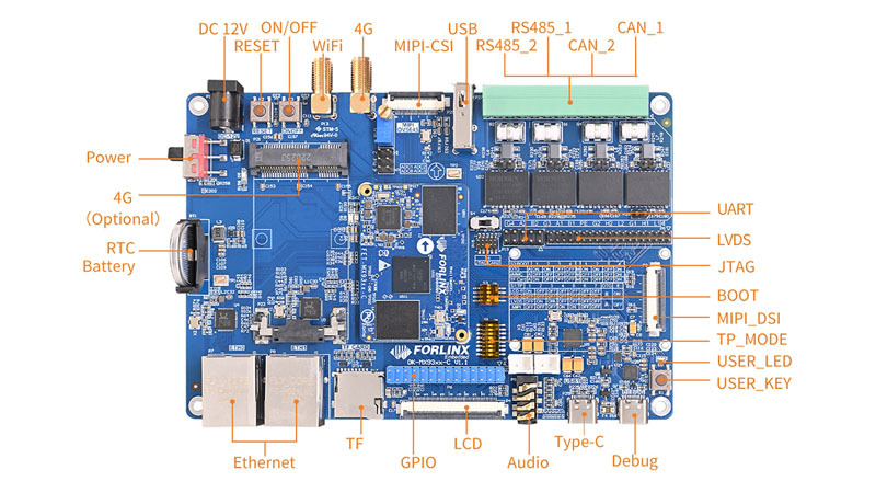
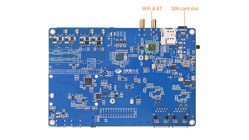
▊ Carrier Board
|
|
| OK-MX9352-C Carrier Board Features | ||
|---|---|---|
| Peripheral Interfaces | QTY | Spec. |
| LCD | 1 | Parallel RGB (RGB888 24-bit), supports up to 1366 × 768 @ 60 fps or 1280 × 800 @ 60 fps |
| LVDS | 1 | Single-channel 8-bit, supports up to 1366 × 768 @ 60 fps or 1280 × 800 @ 60 fps |
| MIPI DSI | 1 | 4-lane, supports up to 1920 × 1200 @ 60 fps |
| TF Card Slot | 1 | Used for OS image flashing; compliant with SD 3.0 protocol |
| 4G Cellular | 1 | Mini-PCIe slot, supports Quectel EC20 module with an external antenna |
| Ethernet | 2 | 2× 10/100/1000 Mbps RJ45 ports; ENET1/ETH1 supports TSN |
| GPIO | 28 | Dual-row pin headers, multiplexed with LCD parallel interface |
| ADC | 4 | 12-bit ADC, supports up to 1 MS/s sampling rate |
| CAN FD | 2 | Equipped with Level 4 ESD, surge, and EFT/pulse protection, featuring galvanic isolation; compliant with CAN FD and CAN 2.0B |
| RS-485 | 2 | Equipped with Level 4 ESD, surge, and EFT/pulse protection, featuring galvanic isolation and automatic direction control |
| USB 2.0 | 2 |
USB1 via Type-C port, supports OS image flashing; USB2 expanded via on-board USB HUB, routed to 4G module, Wi-Fi/BT, USB-to-Quad-UART, and a USB-A female connector |
| UART | 2 | 3.3 V TTL level, broken out via 2.54 mm pitch pin headers |
| Wi-Fi & BT | 1 | On-board BL-M8723DU module, supports 2.4 GHz Wi-Fi and Bluetooth 2.1/4.2 |
| RTC | 1 | On-board RTC battery holder for real-time clock retention |
| Audio | 1 | 1× 4-pole 3.5 mm audio jack (dual-channel headphone + MIC) and 2× speaker jacks |
| Camera | 1 | MIPI CSI interface, compatible with Omnivision OV5645 camera module |
| Keys | 3 | Reset, Power, and User-defined keys |
| LEDs | 1 | User-defined LED indicator |
| GPIO | 9 | 9× GPIO (3.3 V level), with 5 V, 3.3 V, and 1.8 V power rails broken out via 2.54 mm pitch pin headers |
| Debug | 1 | On-board USB-to-UART debug bridge, accessed via Type-C connector |
| JTAG | 1 | 10-pin (2 × 5) header with 2.0 mm pitch |
▊ Accessories
Please click here to get more information about the supported modules and accessories.
▊ Documentation
Reference Manuals
Hardware Related
Product Datasheet
User Guide
Carrier Board Schematic
Carrier Board PCB
SoM Pinmux
Software & BSP
OS Image
Testing Demo
Source Code
Manual
Request a Quote
Fill out the form below for volume pricing or technical specifications. We'll get back to you within 24 hours.
▊ Ordering Information
1. Online Channels: We have an online store on Alibaba and DigiKey. Please contact us for details.
2. Direct Inquiry: For bulk orders, please email our sales team at [email protected].
3. Payment Method: Standard terms: 100% T/T (Telegraphic Transfer) in advance.
1. Dispatch Method: Orders are shipped via international express upon receipt of payment..
2. Lead Time: 5 working days for samples; 6 weeks for bulk orders.
3. Shipping Policy: Shipping and handling fees are the responsibility of the purchaser.
▊ Standard Packing List
▊ Forlinx Recommended Products
Architecture: 2x [email protected]+1x Cortex-M33@250MHz
Frequency: 1.7GHz
RAM: 1GB LPDDR4
ROM: 8GB eMMC
Architecture: 6× [email protected] + 1x Cortex-M7@800MHz + 1x Cortex-M33@333MHz
Frequency: 333MHz ,800MHz,1.8GHz
RAM: 8GB LPDDR4x
ROM: 64GB eMMC
Architecture: 4x [email protected]+1x Cortex-M7@800MHz
Frequency: 1.6GHZ
RAM: 1GB/2GB/4GB LPDDR4
ROM: 8GB/16GB eMMC
Architecture: 4*A53+M7
Frequency: 1.6GHZ
RAM: 2GB/4GB LPDDR4
ROM: 16GB / 32GB eMMC