Comprehensive Guide to i.MX6UL GPIO Control: Methods for Forlinx Embedded Development Boards
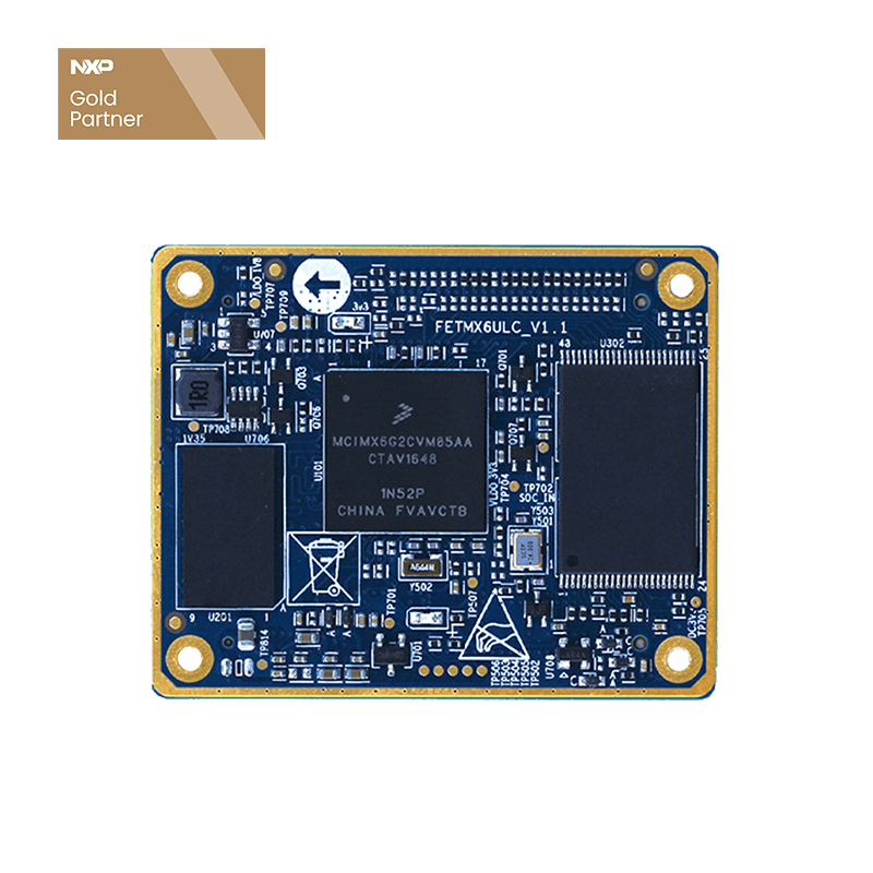
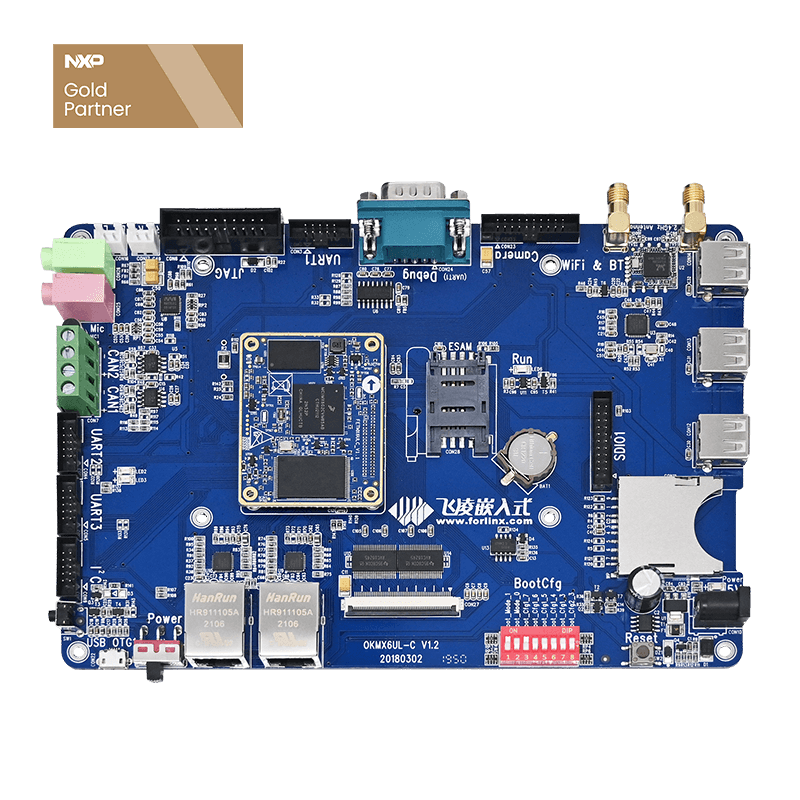
Note: i.MX6UL adds GPIO method, the platform used is the Forlinx Embedded OKMX6UL-C development board, and other platforms can be used as a reference
Method 1: Using iomux method
Add the multiplexed gpio pin in the iomux in the device tree as follows, specifically set the pull-up and pull-down resistance, drive capability, look for the i.MX6UL CPU manual, and modify it accordingly.
MX6UL_PAD_CSI_DATA00__GPIO4_IO21    0x3008
MX6UL_PAD_CSI_DATA01__GPIO4_IO22    0x1f0b1
MX6UL_PAD_CSI_DATA02__GPIO4_IO23    0x1f0b1
MX6UL_PAD_CSI_DATA03__GPIO4_IO24    0x1f0b1
   MX6UL_PAD_SNVS_TAMPER9__GPIO5_IO09    0x1f0b1
MX6UL_PAD_SNVS_TAMPER8__GPIO5_IO08   0x1f0b1
MX6UL_PAD_JTAG_TDO__GPIO1_IO12        0x1f0b1
At the same time modify the device tree file (pins are reused elsewhere)
Compile the device tree. Replace the device tree used in the Forlinx iMX6UL development board.
At this time, you can use the echo command to control:
The command is:
echo $i > /sys/class/gpio/export
echo "out" > /sys/class/gpio/gpio$i/direction
or echo "in" > /sys/class/gpio/gpio$i/direction
echo "1" > /sys/class/gpio/gpio$i/value
echo "0" > /sys/class/gpio/gpio$i/value
echo $i > /sys/class/gpio/unexport
Take controlling GPIO4_IO22 as an example:
1. Calculate the value corresponding to sys/class/gpio GPIOn_IOx = (n-1)*32 + x
GPIO4_IO22=(4-1)*32+22=118
2. Set GPIO4_IO22 as output.
echo 118 > /sys/class/gpio/export Used to notify the system of the GPIO pin number that needs to be exported and controlled
echo "out" > /sys/class/gpio/gpio 118 /direction Control as output
echo "1" > /sys/class/gpio/gpio 118 /value Output is high
or echo "0" > /sys/class/gpio/gpio 118 /value Output is low level
echo 118 > /sys/class/gpio/unexport Notify the system to cancel the export
3. Set GPIO4_IO22 as input.
echo 118 > /sys/class/gpio/export Used to notify the system of the GPIO pin number that needs to be exported and controlled
echo "in" > /sys/class/gpio/gpio 118 /direction Control as input
At this time, connect the pin to high level, the input is high level, otherwise it is low level
echo 118 > /sys/class/gpio/unexport Notify the system to cancel the export
4. In addition, customers can control gpio as input or output through the shell file.
4.1 GPIO output test
Write test scripts vi gpiotest_o.sh
#!/bin/bash
# gpio list gpio (bank-1)*32 + nr
for test in 118 119 120 137 136 12
do
echo Exporting pin $test.
echo $test> /sys/class/gpio/export
echo Setting pin $1.
echo out > /sys/class/gpio/gpio$test/direction
echo $1 > /sys/class/gpio/gpio$test/value
echo $test> /sys/class/gpio/unexport
done
echo complete
Modify script execution permissions: chmod u+x gpiotest_o.sh
Test gpio output is low. Enter the path where the script is located: ./gpiotest_o.sh 0
All GPIO output low level 0V.
Test gpio output as high level. Enter the path where the script is located: ./gpiotest_o.sh 1
All GPIO output high level. The output high level may be different according to the power domain where the pin is located.
In addition, some customers found
echo 118 > /sys/class/gpio/export Used to notify the system of the GPIO pin number that needs to be exported and controlled
echo "out" > /sys/class/gpio/gpio 118 /direction Control as output
echo "1" > /sys/class/gpio/gpio 118 /value Output is high
cat /sys/class/gpio/gpio118/value 0
The reason is shown in the figure below. Customers can find the relevant content from the CPU manual:
The input mode reads the value of psr.
The value of the output is read from the PSR. The output value is written to DR. You can loop back by setting the SION bit.
4.2 GPIO input test
Write test scripts vi gpiotest_i.sh
#!/bin/bash
# gpio list gpio (bank-1)*32 + nr
for test in 118 119 120 137 136 12
do
echo Exporting pin $test.
echo $test> /sys/class/gpio/export
echo in > /sys/class/gpio/gpio$test/direction
gpioval=`cat /sys/class/gpio/gpio$test/value`
echo GPIO $test = $gpioval
echo
echo $test> /sys/class/gpio/unexport
done
echo complete
Modify script execution permissions: chmod u+x gpiotest_i.sh
Test gpio input is low. Enter the path where the script is located ./gpiotest_i.sh
All GPIO inputs are 0.
Test gpio input as high level, such as 5v. Enter the path where the script is located: ./gpiotest_i.sh
All GPIO inputs are 1. (If it is a non-zero value, it is because the corresponding bit is read as 1,you can modify the drivers/gpio/gpio-generic.c file in the kernel source code, and add it to the bgpio get function
return bgc->read_reg(bgc->reg_dat) & bgc->pin2mask(bgc, gpio);
return !!(bgc->read_reg(bgc->reg_dat) & bgc->pin2mask(bgc, gpio));
After modification, the value is 1)
\iomuxc\shell\di\in-test.sh, Copy to the forlinx (for example) directory./in-test.sh 118
\iomuxc\shell\do\close.sh,Copy to the forlinx (for example) directory./close.sh 118
\iomuxc\shell\do\open.sh,Copy to the forlinx (for example) directory./open.sh 118
And \iomuxc\write-117-out-high\test,Copy to the forlinx (for example) directory./test gpio 117 Output is high
Method 2: Create a dev/gpio node.
1. Add the device node definition and its pin definition in the device tree file:
Disabed the functions corresponding to other multiplexed pins to ensure that these pins are not used repeatedly. The pinmux of the pin can be viewed in the imx6ul-pinfunc.h file.
2. Add the gpio driver gpio-user.c in the driver/misc/gpio directory. The name needs to be the same as the driver name in the node definition. Customers can also write the driver themselves. At the same time add Kconfig and Makefile files.
Modify the Kconfig and Makefile files under driver/misc:
Add in driver/misc/Makefile:
obj-y += gpio/
driver/misc/Kconfig,
source "drivers/misc/gpio/Kconfig",
Modify the linux_imx6ul_config file in the root directory and add:
CONFIG_GPIO_USER_INTF=y
3. Compile.
make zImage
make ARCH=arm CROSS_COMPILE=arm-fsl-linux-gnueabi- dtbs
4. Copy the previously generated zImage, imx6ul-14x14-evk.dtb to the system directory of the SD card, and burn it to the SD card.
There are gpio nodes under dev.
Use gpio-test.c as the user test program. Compile to gpio-test.
Use gpio-test in 2 to test DI.
Use gpio-test out 0 1 to test that the output of DO1 is high.
Use gpio-test out 0 0 to test that the output of DO1 is low.
Dear friends, we have created an exclusive embedded technical exchange group on Facebook, where our experts share the latest technological trends and practical skills. Join us and grow together!


