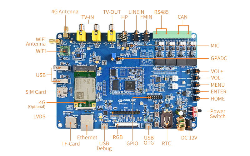
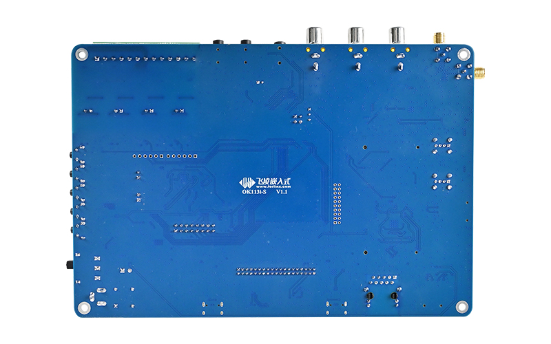
OK113i-S Single Board Computer Based on Allwinner T113-i
The OK113i-S single board computer consists of user-friendly carrier board and FET113i-S System on Module (SoM), powered by Allwinner’s T113-i advanced application processor. It integrates dual-core Cortex-A7 CPU and single-core HiFi4 DSP to provide highly efficient computing power. It supports full format decoding and encoding. Integrated multi audio interfaces can provide the perfect voice interaction solution. T113-i comes with extensive connectivity to facilitate product expansion, such as USB, SDIO, UART, SPI, CAN, Ethernet, and so on.
Half-hole package helps to make your product easy to cope with vibration environment. Half-hole package takes better anti-vibration performance on carrier board directly, enhancing its connection with carrier board for excellent anti-vibration performance.
OK113i-S SBC
Cost-Efficient Industrial SoC
Compared with the equivalent T113-S3, T113-i is an industrial processor(operating temperature width -40℃~+85℃) up to 1.2GHz, making it applicable for typical industrial scenarios.
ARM, DSP, and RISC-V Multi-Core Running Together
T113-i SoM can be powered on or shut down by a determined program;
Besides, Cortex-A7, RISC-V and DSP multi-core can run together with DSP for multi-media and digital signal processing, and RISC-V for real-time tasks processing.
Interface Resources
Advancing Multi-Media Performance
T113-i supports multiple full format decoding such as H.265 (4K@30fps), MPEG-4 (1080p@60fps), JPEG (1080p@60fps), and so on, and supports JPEG/MJPEG( 1080p@60fps) encoding;
Besides, it supports 8-bit parallel CSI and CVBS video input, CVBS, RGB, 2-lane LVDS and 4-lane MIPI-DSI video output;
A built-in DSP provides high-efficient audio computing power.
Target Applications
▊ Video
Forlinx lauched FET113i-S SoM & OK113i-S SBC Based on Allwinner T113-i
▊ Hardware Features
|
FET113i-S SoM Basic Features |
|
|---|---|
|
CPU |
Allwinner T113-i CPU: T113-i VPU:
• Video Decoding: • Video Encoding: JPEG/MJPEG up to 1080p@60fps RISC-V: C906@1008MHz DSP: 600MHz |
|
RAM |
512MB/256MB DDR3 |
|
ROM |
8GB eMMC/256MB SPI Nand Flash |
| Voltage input | DC 5V |
|
Operating temp |
-40℃~+85℃/-25℃~+85℃ |
|
Package |
Half-hole soldering(146 pins, 1mm pitch) |
|
Dimensions |
35mm x 44mm |
|
OS version |
Linux5.4.61 |
|
Firmware installation |
• TF card • USB OTG |
|
FET113i-S SoM Functional Parameters |
|||
|---|---|---|---|
|
Peripheral |
QTY |
Spec. |
|
|
RGB_LCD |
1 |
DE/SYNC, up to 1920x1080@60fps |
Muliti-plexed and alternative |
|
LVDS |
1 |
Single link, up to 1366×768@60fps; Dual link, up to 1920×1080@60fps |
|
|
MIPI-DSI |
1 |
4-lane, up to 1920×1200@60fps |
|
|
CVBS_OUT |
1 |
Supports NTSC and PAL, 10-bit pixel depth |
|
| CSI | 1 |
8-bit digital camera, up to 148.5MHz |
|
| CVBS IN | 2 | Supports NTSC and PAL, 10-bit video ADCs | |
| Audio out | 2 | A pair of stereo headphone output, a pair of differential Lineout | |
| Audio in | 5 |
Three differential/ single MIC, a stereo LINEIN input, a stereo FMIN input |
|
| IIS | ≤3 | Host/ slave mode optional, sampling rate 8kHz to 384kHz | |
| DMIC | 1 |
PDM MIC, sampling rate 8kHz to 48kHz |
|
| OWA | 1 |
S/PDIF |
|
| USB DRD | 1 | Host mode up to 480Mbit/s, slave mode up to 480Mbit/s | |
| USB Host |
1 |
Host mode up to 480Mbit/s | |
|
EMAC |
1 |
10/100/1000 Mbit/s, supports RGMII and RMII | |
| UART |
≤5 |
Up to 4Mbit/s, except for DEBUG UART, there are 5 UART for users | |
|
SPI |
1 |
SPI0-SPI1, SPI0 is used by SoM, so only SPI1 can be used by users, SPI1 supports both SPI mode and DBI mode | |
|
TWI |
≤3 |
TWI0-TWI3, compatible with I2C, up to 400 kbit/s, TWI3 is used by SoM and not available | |
|
CIR |
1 |
Supports 1x infrared RX and 1x infrared TX | |
|
PWM |
≤7 |
PWM0-PWM7, PWM7 is used by SoM, output rating from 0 to 24MHz or 100MHz | |
|
GPADC |
≤2 |
SAR ADC, 12-bit resolution, 8-bit accuracy, sampling rate up to 1MHz, sampling power up to 1.8V | |
|
TPADC |
1 |
4-wire resistive touching panel input detecting | |
|
LRADC |
1 |
Low speed ADC input, for key detecting | |
|
CAN |
2 |
CAN2.0B | |
|
SD |
2 |
SDC0 is only available for 3.3V IO, it’s configured to SD card, SDC1 is only available for 3.3V IO | |
|
JTAG |
1 |
2x 5 pin headers with pitch of 2.0mm | |
▊ OK113i-S Carrier Board

|

|
| OK113i-S Carrier Board Features | |||
|---|---|---|---|
|
Peripheral interfaces |
QTY |
Spec. |
|
|
RGB_LCD |
1 |
RGB666, both capative and resistive touching are supported, backlight is adjustable |
|
|
LVDS |
1 |
Dual asynchronous channels(8x data, 2x clock), capactive touching is supported, backlight is adjustable |
|
|
TV-OUT |
1 |
RCA jack |
|
|
TV-IN |
1 |
RCA jack |
|
|
Audio |
/ |
A 4-position headphone jack, CTIA, stereo, contains MIC; An on-board electret MIC; A LineIN jack; An DMIN jack; two stereo speaker up to 4Ω 1.9W |
|
|
Audio in |
5 |
Three differential/ single MIC, a stereo LINEIN input, a stereo FMIN input |
|
|
Ethernet |
1 |
10/100/1000Mbps adaptive, RJ45 |
|
|
TF card |
1 |
For OS image flashing |
|
|
4G |
1 |
Mini-PCIe slot, compliant with USB2.0, on-board SMA antenna; Nano-SIM card slot |
|
|
WiFi&BT |
1 |
Wi-Fi: IEEE 802.11 a/b/g/n WIFI, up to 150Mbps; |
|
|
GPADC |
2 |
Pin headers, can be tested by sliding rheostat |
|
|
KEYADC |
5 |
||
| RTC |
1 |
||
|
UART |
1 |
Pin headers with pitch of 2.54mm |
|
|
SPI |
1 |
Pin headers with pitch of 2.54mm |
|
|
CAN |
2 |
Electrical isolation, CAN2.0B |
|
|
RS485 |
2 |
Electrical isolation, auto-control transceiving direction |
|
|
KEY |
3 |
1 for OS image flashing, 1 for reset, one for user’s definition |
|
|
LED |
1 |
Blue, user defined LED |
|
|
USB Type-A |
2 |
USB2.0, only for USB Host |
|
|
USB Type-C |
1 |
USB2.0, host/ slave adaptive |
|
|
USB Debug |
1 |
USB type-C port, default baud rate 115200 |
|
|
JTAG |
1 |
2x 7-pin headers with pitch of 2.0mm for A7 and RISC-V debugging |
|
▊ Downloads
Catalog:
Forlinx Catalog Manual
Datasheet:
FET113i-S SoM and OK113i-S SBC introduction
|
Linux5.4.61 |
User manual, compiling guideline, GIT source, 3P tool and lib, reference files from Allwinner, kernel source code, file system, OS image, VM ubuntu image, SD card making tool |
| Hardware | User manual, carrier board schematic, carrier board PCB(CAD), datasheet, carrier board and SoM DXF files, pinmux sheet |
▊ Accessories
Please click here to get more information about the supported modules and accessories.
▊ Technical Support
1. Files to be provided after buying
Hardware related: datasheet, user guide, carrier board schematic, carrier board PCB, SoM pinmux;
Firmware related: OS image, testing demo, source code, manual;
Compiling environment
2. Fast response after-sale technical support service
Contact Us
Welcome to get in touch with us, our experts will reply to your email within 24 hours.
▊ How To Buy
1. Order Online
We have an online store on Alibaba, please contact us for details.
2. Order Offline
Please send your inquiry to [email protected];
3. Payment Terms
100% T/T in advance.
▊ Shipment
1. Delivery: Goods will be shipped by express upon the receipt of the payment;
2. Lead time: Goods will be shipped out within five working days for sample orders and 6 weeks for bulk orders;
3. Shipping charge: Buyers should bear the shipping cost.
Product Shipping List |
|
|---|---|
| FET113i-S System on Module | 1 |
| OK113i-S Carrier Board | 1 |
| WiFi Antenna | 1 |
| Power adapter | 1 |
| IPEX Jumper | 1 |
| Type-A to Type-C Adapter Cable | 1 |
| Warranty Card | 1 |
| Packaging Box | 1 |
| Get the Price | |
▊ Other Forlinx Hot Products
Architecture: 2×Cortex-A7+RISC-V+DSP
Frequency: 1.2GHz
RAM: 512/256MB DDR3L
ROM: 256MB NandFlash,8GB eMMC
System: Linux 5.4.61
Architecture: 4×U74
Frequency: 1.5GHz
RAM: 2GB/4GB LPDDR4
ROM: 32GB eMMC
System: Linux 5.15.0
Architecture: Cortex-A53
Frequency: 1.5GHz
RAM: 2GB DDR3L
ROM: 8GB eMMC
System: Linux4.9+QT5.12
Architecture: Cortex-A7
Frequency: 800MHz
RAM: 256MB DDR3,512MB DDR3
ROM: 256MB NandFlash,4GB eMMC
System: Linux4.1.15+QT5.6


