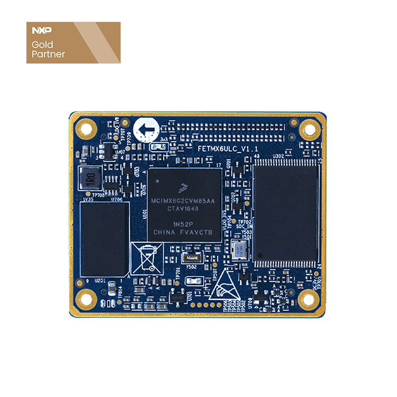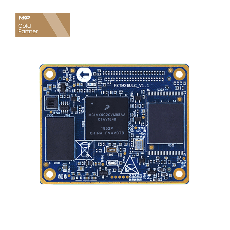
Carrier Board PCB Designing Tips for SoM FETMX6UL-C Users
Power Sequence
PMIC_ON_REQ current drive power is too weak, the power sequence in single board computer is controlled by field effect tube, the grid pull-down resistor value should be above 100K, otherwise, it may cause the tube failure(indicator on SoM doesn't work, and no printing information output).
BOOT Option (LCD)
All 24 data lanes of the LCD are for booting configuration, please do not do pulling up or down operation to them, otherwise, it may cause the SoM boot failure(SoM voltages are normal and LED lighten up, but no serial port printing information output).
If the LCD pins are not in high resistance mode during powering moment, single board computer may fail to boot, to avoid this, we kindly suggest users adding a frame chip between LCD and CPU, chipset SN74AVC16245 is recommended.
The carrier board is designed with LCD DE mode, if users want to change to line field mode, please solder R139 and R140 with 0Ω resistors, meanwhile, remove R144 resistor(in line field mode, OTG can not work in host mode).
USB
When working with USB, please circuit USB_OTG1_VBUS and USB_OTG2_VBUS to 5V power, otherwise, you may get errors. If to connect USB_OTG1 to HUB chip, please pull-down ID pin.
Key
Power switch ONOFF can be suspended if it's not used.


